Battery Cell, Module or Pack? A Clear Guide to Each Level
Reading time: 8 minutes

Share
The terms battery cell, battery module and battery pack describe different levels of a battery system. The cell carries out the electrochemical reaction that stores energy. The module connects and supports a number of cells. The pack combines the energy-storage components with the controls, protection and external interfaces required by the final application.
Although this three-stage structure is widely used, it is not compulsory. Some batteries use cell-to-pack construction, meaning that cells are integrated directly into the main pack without separate module housings.
Cell, Module and Pack Comparison
| Point of Comparison | Cell | Module | Pack |
|---|---|---|---|
| Level | Individual electrochemical unit | Intermediate cell assembly | Complete battery system |
| Function | Store and release energy | Connect and support cells | Provide controlled power to equipment |
| Main contents | Electrodes, electrolyte, separator and casing | Cells, interconnects, insulation and support structure | Cells or modules, BMS, protection, enclosure and terminals |
| Thermal management | Limited to the cell construction | May include local cooling components | Designed for the complete battery |
| Ready for use | Normally no | Normally no | Generally yes |
What Is a Battery Cell?
A battery cell is the basic functional unit of a rechargeable battery. It stores electrical energy chemically during charging and releases that energy as electrical current during discharge.
One cell may operate a compact electronic device, but most traction, marine, caravan and stationary storage systems require many cells to achieve their target voltage, capacity and current output.
Internal Cell Components
- Positive electrode: Influences nominal voltage, energy density, durability and safety.
- Negative electrode: Stores lithium ions during charging.
- Electrolyte: Enables ions to move between the electrodes.
- Separator: Prevents electrical contact between the electrodes while allowing ion movement.
- Current collectors: Carry electrons between the active materials and terminals.
- Tabs or terminals: Provide the electrical connection to the wider battery system.
- Cell casing: Holds the internal materials and provides mechanical protection.
The chemistry used inside the cell affects voltage, charge profile, energy density, power output, temperature tolerance and cycle life.
Common Cell Formats
| Format | Construction | Advantages | Design Requirements |
|---|---|---|---|
| Cylindrical | Rolled electrodes inside a metal cylinder | Rigid casing, established manufacturing and standard sizes | More interconnections and unused space between cells |
| Prismatic | Rectangular metal housing | Efficient rectangular packaging and high capacity per cell | Correct compression and thermal control may be required |
| Pouch | Flexible laminated enclosure | Low casing mass and adaptable dimensions | Needs external support and allowance for expansion |
The cell format does not define the chemistry. Cylindrical, prismatic and pouch cells can all be manufactured with different active materials.
LiFePO4 cells normally have a nominal voltage of approximately 3.2V. Many NMC and NCA cells operate at around 3.6V to 3.7V, while LTO cells are typically close to 2.3V.
Reading Cell Specifications
Important cell specifications include:
- Nominal voltage
- Capacity in amp-hours
- Energy in watt-hours
- Maximum continuous current
- Short-duration peak current
- Permitted charging voltage and current
- Charging and discharging temperature ranges
A 3.2V 100Ah LiFePO4 cell has a nominal energy rating of:
3.2V × 100Ah = 320Wh
This figure does not guarantee 320Wh at the connected appliance. Battery cut-off settings, inverter efficiency, cable losses, temperature and discharge rate all influence usable energy.
What Is a Battery Module?
A battery module connects several selected cells into a mechanically stable electrical subassembly. It gives the cell group a defined voltage, capacity, shape and thermal arrangement.
Modules simplify the manufacture, testing and installation of large batteries. However, a module may still need a master controller, high-current protection, final enclosure and external connections before it can operate as a finished battery.
Series and Parallel Connections
Cells within a module can be connected in three main ways:
- Series: Raises voltage while Ah capacity remains unchanged.
- Parallel: Raises capacity and current capability while voltage remains unchanged.
- Series-parallel: Raises both voltage and capacity.
A module can contain busbars, cell holders, compression plates, insulation, voltage-sensing leads, temperature sensors and a supporting frame.
Correct interconnection design is essential. Busbars and fasteners must carry the full current without creating excessive resistance or localised heating.
Cell Consistency
Cells sharing the same module should have similar capacity, voltage, internal resistance, self-discharge behaviour and temperature response.
A weaker cell can determine the usable capacity of the entire series string. If one 100Ah cell reaches its lower voltage limit after 92Ah, the BMS may stop the module at that point even though the remaining cells have not been fully discharged.
Good matching makes balancing more effective and helps parallel groups share current more evenly.
Structural and Thermal Functions
The module structure keeps cells in position, maintains insulation and controls movement caused by vibration or normal expansion. Depending on power level, thermal components may include conductive plates, thermal pads, ventilation channels or liquid-cooling interfaces.
Some modules contain local balancing or monitoring boards. This does not necessarily make them complete packs, as the master BMS and main switching hardware may remain elsewhere.
What Is a Battery Pack?
A battery pack is the final battery assembly designed to supply a motor, inverter, vehicle, appliance or energy-storage system. It includes the equipment needed to control and protect the stored energy.


Typical Pack Components
- Battery cells or modules
- Main busbars and internal cables
- External output terminals
- A battery management system
- Fuses, breakers, contactors or MOSFETs
- Voltage, current and temperature sensors
- Service disconnect and pre-charge components
- Protective enclosure
- Communication connections
- Heating, ventilation or cooling components
A compact 12V LiFePO4 battery may use MOSFETs inside the BMS to interrupt current. A high-voltage traction pack requires contactors, pre-charge control, isolation monitoring and a more substantial enclosure.
BMS and System Protection
The BMS supervises the battery’s operating conditions. Its functions may include:
- Individual cell-voltage monitoring
- Pack-voltage and current measurement
- Temperature monitoring
- Overcharge and over-discharge protection
- Short-circuit and overcurrent response
- Cell balancing
- State-of-charge calculation
- Control of contactors or MOSFETs
- Fault recording
- Communication with the charger, inverter or vehicle
The finished battery’s current capability is determined by its complete design. High-output cells do not compensate for an undersized BMS, terminal, fuse or internal conductor.
Enclosure and Temperature Control
The enclosure may need to withstand vibration, impact, dust, moisture, salt exposure and repeated changes in temperature. The required protection level depends on whether the battery is installed inside a motorhome, boat, industrial vehicle, cabinet or outdoor energy-storage system.
LiFePO4 batteries also require suitable low-temperature charging protection. A battery may discharge at temperatures below freezing while still prohibiting charging until the cells become warmer.
How Series and Parallel Connections Change a Battery
Series Configuration
Connecting cells in series adds their voltages. Ah capacity remains equal to the capacity of one cell.
Total voltage = nominal cell voltage × series cell count
Four 3.2V 100Ah cells in series form a 4S arrangement with:
- 12.8V nominal voltage
- 100Ah capacity
- 1.28kWh nominal energy
Parallel Configuration
Connecting cells in parallel keeps voltage unchanged while capacities add. Two 3.2V 100Ah cells in parallel provide 3.2V, 200Ah and 640Wh.
Parallel operation requires carefully matched cells and balanced connections. Differences in temperature, internal resistance or interconnection resistance can cause uneven current sharing.
Series-Parallel Examples
| Layout | Cell Count | Voltage | Capacity | Energy |
|---|---|---|---|---|
| 4S | 4 | 12.8V | 100Ah | 1.28kWh |
| 4S2P | 8 | 12.8V | 200Ah | 2.56kWh |
| 8S | 8 | 25.6V | 100Ah | 2.56kWh |
| 16S | 16 | 51.2V | 100Ah | 5.12kWh |
| 16S2P | 32 | 51.2V | 200Ah | 10.24kWh |
The same energy capacity can be delivered through different voltage and current combinations. The chosen configuration affects inverter compatibility, cable cross-section, charger requirements and protective-device ratings.
Module-Based and Cell-to-Pack Designs
In a traditional architecture, cells are first assembled into modules. The modules are then mounted inside the pack. This can simplify manufacturing, testing, fault diagnosis and the creation of several pack sizes from a common module.
The additional module hardware adds interfaces, structural parts, weight and occupied volume.
Cell-to-pack construction removes this intermediate layer. It can improve packaging efficiency and reduce component count, but cell restraint, electrical isolation, thermal management and fault containment must then be handled by the main pack structure.
Typical Applications
Electric Vehicles and Industrial Machinery
Electric vehicles can contain hundreds or thousands of cells, depending on cell size, chemistry, pack voltage and energy target. Industrial vehicles, telecom systems and large uninterruptible power supplies often use modular construction to simplify scaling and maintenance.
Stationary Energy Storage
A rack battery may contain cells, local monitoring, an enclosure, terminals and communication ports. A complete energy-storage installation can then combine several rack units with an inverter, master controller, cooling system and site-level protection.
Before installation, confirm which functions are included in the rack battery and which must be provided externally.
Motorhomes, Caravans, Boats and Golf Carts
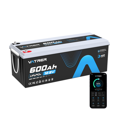
Lithium batteries for motorhomes, caravans, boats, trolling motors and golf carts are generally finished battery packs.
They normally include the cells, internal BMS, enclosure, terminals and temperature monitoring needed for installation. Some models also provide Bluetooth monitoring, heating or an integrated display.
When evaluating a Vatrer LiFePO4 lithium battery, compare nominal voltage, available Wh, continuous current, short-term peak demand, charger compatibility, dimensions, terminal arrangement and temperature protection.
Choosing the Right Battery Level
Complete Packs
A complete pack is usually the correct option for a motorhome, caravan, boat, solar installation, golf cart or replacement battery. It should provide defined terminals, current limits, charge requirements and protection behaviour.
Battery Modules
Modules are intended for systems in which the pack-level controls, enclosure, switching devices, thermal management and communication will be engineered separately.
Individual Cells
Cells offer the greatest design flexibility but require specialist knowledge. A safe cell-level build needs correct cell matching, busbars, insulation, mechanical restraint, fusing, BMS configuration, temperature sensing, charging limits and enclosure design.
High-capacity lithium cells can produce extremely high fault current. Incorrect tools, exposed conductors, loose connections or reversed polarity can create dangerous heat and arcing.
Final Summary
The cell performs the electrochemical work. The module organises several cells into a manageable subassembly. The pack controls and protects the complete energy source.
For most users, a tested complete pack is the appropriate choice. Modules suit engineered systems, while individual cells are intended for experienced manufacturers and battery builders.
Before selecting a battery, determine the required voltage, watt-hours, continuous current, peak current, available space, charging equipment and expected temperature range. These values reveal far more about suitability than the Ah rating on its own.
Share