Batteries in Series vs. Parallel: European Wiring Guide
Reading time: 7 minutes

Share
Series and parallel battery wiring is a key part of designing a reliable DC energy system for a campervan, motorhome, boat, off-grid solar installation, backup system, or other mobile and stationary application.
Changing the way batteries are connected changes battery-bank voltage and Ah capacity, while also influencing current, cabling, charger selection and equipment compatibility. Two identical 12V 100Ah batteries can be configured as either a 24V 100Ah bank or a 12V 200Ah bank.


What Is the Difference Between Batteries in Series and Parallel?
Series wiring increases voltage by connecting batteries one after another. Parallel wiring keeps nominal voltage unchanged while increasing Ah capacity. Series-parallel wiring combines matched strings when both values need to increase.
Batteries Connected in Series
Connect the positive terminal of one battery to the negative terminal of the next. The free terminals at opposite ends of the string become the main battery-bank connections.
2 × 12V 100Ah batteries in series = 24V 100Ah
Total series voltage = V₁ + V₂ + V₃ + ...
Series capacity = Ah rating of one matched battery
Series wiring is useful when the DC equipment requires a higher operating voltage, including many 24V and 48V inverter-based systems.
Batteries Connected in Parallel
In parallel, all positive terminals connect to a common positive path and all negative terminals connect to a common negative path. Nominal voltage stays unchanged, while the Ah capacities combine.
2 × 12V 100Ah batteries in parallel = 12V 200Ah
Parallel voltage = voltage of one matched battery
Total parallel Ah = Ah₁ + Ah₂ + Ah₃ + ...
Series vs. Parallel Comparison
| Electrical Value | Series | Parallel |
|---|---|---|
| Voltage | Increases as battery voltages add | Remains unchanged |
| Ah capacity | Remains the same | Increases as capacities add |
| Total nominal energy | Wh from all batteries adds | Wh from all batteries adds |
| Main reason to use it | Reach the required system voltage | Increase energy capacity at the same voltage |
| Charger requirement | Must suit full string voltage | Must suit the nominal system voltage |
| Connection | Positive to negative | Positive to positive and negative to negative |
What Happens to Voltage, Ah, Wh and Current?
Voltage and Capacity
Using four 12V 100Ah batteries provides a useful comparison.
Four in series:
12V + 12V + 12V + 12V = 48V
Battery bank = 48V 100Ah
Four in parallel:
100Ah + 100Ah + 100Ah + 100Ah = 400Ah
Battery bank = 12V 400Ah
Use Watt-Hours to Compare Stored Energy
Watt-hours are especially useful when comparing battery banks at different nominal voltages.
Wh = V × Ah
One 12.8V 100Ah LiFePO4 battery = 1,280Wh
Two in series = 25.6V × 100Ah = 2,560Wh
Two in parallel = 12.8V × 200Ah = 2,560Wh
Both arrangements contain the same combined nominal battery energy. Only the voltage/Ah relationship has changed.
System Voltage and Operating Current
A higher DC system voltage reduces the current required to supply the same power. This can be relevant in larger inverter systems because high DC current increases conductor and connection requirements.
Power = Voltage × Current
For an ideal 2,400W load:
- 12V = 200A
- 24V = 100A
- 48V = 50A
These values are simplified examples. Actual current depends on real operating voltage, inverter efficiency, cable resistance and the load. Also remember that a 230V AC inverter output does not mean the battery itself is a 230V battery bank—the inverter's permitted DC input voltage still determines the battery-side design.
How Does a Series-Parallel Configuration Work?
Series-parallel wiring is used when neither voltage nor capacity can be reached with series or parallel wiring alone. Matching batteries are first connected into identical series strings, and those strings are then paralleled.
Identical Battery Strings Matter
Each parallel string should contain the same number and model of batteries, with an equivalent electrical path to the common connection point. Series determines string voltage, while the number of parallel strings determines total Ah capacity.
Understanding S and P Notation
- 2S2P: two batteries in series in each of two parallel strings.
- 4S2P: four batteries per series string with two strings in parallel.
- 4S4P: four batteries per series string with four strings in parallel.
4S2P Example
A 4S2P battery bank built with eight matching 12.8V 100Ah LiFePO4 batteries produces:
One four-battery series string:
4 × 12.8V = 51.2V
Capacity = 100Ah
Two matching strings in parallel:
100Ah × 2 = 200Ah
Completed bank = 51.2V 200Ah
Nominal energy = 10,240Wh
What Should You Check Before Connecting Batteries?
Use Compatible Batteries
Use batteries that the manufacturer approves for the planned multi-battery configuration. Matching chemistry, model, voltage, capacity, age and condition improves consistency. Refer to the manufacturer's installation and connection guidance.
Match Voltage Before Parallel Connection
Check battery or string voltage before joining them in parallel. A significant voltage difference can create a high equalisation current immediately after connection.
Check BMS Connection Limits
LiFePO4 battery BMS designs vary. Confirm maximum series quantity, parallel quantity, supported series-parallel layout, continuous current, peak current and charging restrictions for the specific battery.
Plan Cable Size and Protection Properly
Select cables according to current, conductor length, allowable voltage drop, installation conditions and equipment ratings. Protective devices should be selected for the specific architecture rather than copied from a generic diagram.
Pre-Connection Checklist
- Compatibility: Confirm the batteries are suitable for the same bank.
- Manufacturer limits: Check supported series and parallel quantities.
- Voltage/SOC: Match batteries or strings before paralleling.
- Polarity: Confirm terminal identification.
- Cabling: Size cables and connectors for the expected current.
- Protection: Use suitable fuses, circuit breakers and isolation devices.
- Charger: Match charger voltage and chemistry profile.
- Equipment: Verify DC input voltage across the complete system.
- Isolation: Disconnect loads and charging sources during assembly.
How Do You Wire Batteries in Series or Parallel?
Series Wiring
Connect the positive terminal of the first battery to the negative terminal of the second, then continue the same pattern through the string. The remaining terminals form the main battery-bank output.
- Isolate chargers and loads.
- Check series-operation approval.
- Make the positive-to-negative interconnections.
- Verify polarity and specified terminal torque.
- Measure final voltage before reconnecting equipment.
Parallel Wiring
Connect battery positives to a common positive path and battery negatives to a common negative path. In larger banks, an electrically balanced layout and correctly designed busbars can improve current sharing.
- Isolate the battery system.
- Check voltage and SOC matching.
- Connect all positive paths.
- Connect all negative paths.
- Inspect protection, terminals and cable routing.
- Measure the completed bank voltage.
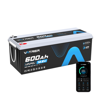
If a campervan, motorhome, boat or off-grid installation needs significantly more energy at 12V, using one larger battery can sometimes be simpler than adding several parallel branches. The Vatrer 12V 600Ah self-heating lithium battery offers 7.68kWh of usable energy, a 300A BMS and self-heating capability, reducing the number of separate inter-battery connections required in a large 12V installation.
Series-Parallel Wiring
First assemble each identical series string and measure its voltage. Once the strings satisfy the required matching conditions, connect their positive outputs to the positive bus and their negative outputs to the negative bus.
- Build matching series strings.
- Measure every string.
- Compare voltages before paralleling.
- Connect matching strings in parallel.
- Verify the final bank before connecting equipment.
How Should Series and Parallel Batteries Be Charged?
Charging Series Batteries
The charger must be suitable for the complete series-bank voltage and battery chemistry. Two compatible 12V batteries in series therefore require charging equipment for the corresponding 24V battery system.
Where a vehicle or other application requires a 48V-class battery system, using a native-voltage battery can reduce the number of series interconnections. The Vatrer 48V 105Ah lithium battery includes a matched charger and LCD display and supports up to 10.24kW continuous output through its 200A BMS.
Charging Parallel Batteries
The charger voltage stays equal to the nominal voltage of the parallel bank. The larger combined Ah capacity means charge time will increase when charger current remains unchanged.
Charging Series-Parallel Batteries
Charge a series-parallel bank according to its final system voltage and chemistry. Parallel strings should be closely matched, and batteries or strings should be checked after installation, servicing or replacement as required.
Which Configuration Should You Choose?
Define the DC System Voltage
Start with the permitted DC input voltage of the inverter, motor controller, distribution system or other equipment. This is the first constraint in the battery-bank design.
Estimate the Required Energy
Then calculate the energy needed for the desired operating time.
Required energy (Wh) = Load power (W) × Runtime (h)
For a 500W load running for four hours:
500W × 4h = 2,000Wh
Allow additional capacity for conversion losses, temperature, reserve energy and usable discharge limits.
Typical Battery-Bank Layouts
| Requirement | Batteries | Configuration | Result |
|---|---|---|---|
| 24V bank | 2 × 12V 100Ah | 2S | 24V 100Ah |
| 48V bank | 4 × 12V 100Ah | 4S | 48V 100Ah |
| More 12V capacity | 2 × 12V 100Ah | 2P | 12V 200Ah |
| Larger 12V capacity | 4 × 12V 100Ah | 4P | 12V 400Ah |
| 24V plus extra capacity | 4 × 12V 100Ah | 2S2P | 24V 200Ah |
| 48V plus extra capacity | 8 × 12V 100Ah | 4S2P | 48V 200Ah |
For a larger 48V-class residential or off-grid energy-storage system, a native 51.2V rack battery can simplify the DC architecture compared with creating long strings from 12V batteries. A Vatrer 51.2V 100Ah server rack battery provides 5.12kWh per unit with CAN/RS485 communication, Bluetooth monitoring and a modular rack format.
Key Points to Remember
Series wiring adds voltage. Parallel wiring adds Ah capacity. Series-parallel wiring lets you increase both. However, the correct configuration always starts with the required system voltage, followed by the required energy in Wh and the current that the equipment will draw.
As battery banks become larger, fewer higher-capacity or native-voltage batteries can also be worth considering because they can reduce interconnect cables, terminals and maintenance points.
1 comment
Mit Bestem Dank und Freundlichen Grüßen