Battery Cells, Modules and Packs: A Practical Comparison
Reading time: 9 minutes

Share
Battery cells, modules, and packs are connected parts of the same energy-storage system, but they are not interchangeable terms. A cell is the unit that actually stores energy. A module combines several cells into a supported group. A pack adds the controls, protection, enclosure, and connections required by the final application.
The three-layer structure is common rather than universal. Some manufacturers use a cell-to-pack layout that installs cells directly inside the finished enclosure. Whether modules are present or not, the important difference is how much of the battery system has already been engineered around the cells.
Quick Comparison of Cells, Modules and Packs
| Feature | Cell | Module | Pack |
|---|---|---|---|
| Definition | One electrochemical energy-storage unit | Several connected and supported cells | A complete battery built for an application |
| Primary job | Store and release energy | Provide a defined cell-group voltage and capacity | Deliver controlled and protected power |
| Typical hardware | Electrodes, electrolyte, separator, casing | Cells, busbars, sensors, insulation, support structure | Cells or modules, BMS, protection, enclosure, terminals |
| Monitoring | Normally none at system level | May include voltage and temperature sensing | Usually includes complete system monitoring |
| Installation-ready | No | Usually no | Usually yes |
What Is a Battery Cell?
A battery cell is the smallest independently functioning part of a rechargeable battery. It receives electrical energy during charging, stores that energy through a chemical reaction, and releases current during discharge.
A single cell can operate a small device, but larger applications need multiple cells. A recreational vehicle, cottage power system, fishing boat, golf cart, telecom backup system, or electric vehicle may require higher voltage and far more energy than one cell can supply.
Main Components Inside a Cell
- Positive electrode: Helps determine voltage, energy density, lifespan, and safety behaviour.
- Negative electrode: Stores lithium ions while the cell charges.
- Electrolyte: Carries ions between the positive and negative electrodes.
- Separator: Keeps the electrodes physically apart while permitting ion flow.
- Current collectors: Conduct electrons to and from the cell terminals.
- Tabs or terminals: Connect the cell to the next level of the battery system.
- Outer casing: Contains the active materials and provides mechanical protection.
Cell chemistry has a direct influence on nominal voltage, charge profile, power output, temperature tolerance, cycle life, and overall safety characteristics.
Cylindrical, Prismatic and Pouch Cells
| Format | Description | Benefits | Considerations |
|---|---|---|---|
| Cylindrical | Rolled electrodes inside a rigid metal can | Durable, standardized, widely manufactured | May require more cells and more interconnections |
| Prismatic | Large rectangular cell in a metal enclosure | Efficient packaging and fewer cells per system | Often needs proper compression and heat control |
| Pouch | Flexible laminated outer casing | Lightweight and adaptable dimensions | Requires structural support and expansion allowance |
Cell format and cell chemistry are separate choices. A prismatic cell, for example, may use LiFePO4 or another lithium chemistry.
LiFePO4 cells are commonly rated at about 3.2V nominal. Many NMC and NCA cells operate around 3.6V to 3.7V nominal, while LTO cells are generally near 2.3V.
Voltage, Capacity and Energy
The main electrical ratings of a cell include nominal voltage, Ah capacity, Wh energy, continuous current, peak current, and charging limits.
Energy is calculated by multiplying nominal voltage by capacity:
Watt-hours = volts × amp-hours
A 3.2V 100Ah LiFePO4 cell therefore contains approximately:
3.2V × 100Ah = 320Wh
Actual usable energy will be lower in many installations. Cold conditions, high current draw, wiring resistance, inverter losses, and BMS voltage cutoffs can all affect runtime.
What Is a Battery Module?
A battery module is a mechanically supported group of electrically connected cells. It makes larger systems easier to assemble, cool, inspect, test, and install.
The module provides a defined voltage, Ah capacity, physical size, and thermal path. It may include local sensing electronics, but it usually still depends on pack-level controls and protection.
Electrical Connections Inside a Module
Cells may be arranged in series, parallel, or a combined series-parallel layout.
- Connecting cells in series raises voltage.
- Connecting cells in parallel raises capacity and current capability.
- Combining both methods raises voltage and capacity.
A typical module may include:
- Matched cells
- Busbars and cell interconnects
- Cell holders or spacers
- Compression plates
- Electrical insulation
- Voltage-sensing leads
- Temperature sensors
- A frame or housing
The current-carrying parts must be designed for the module’s full output. Loose connections or undersized busbars can produce heat, voltage drop, and premature shutdown even when the cells remain healthy.
Why Cell Matching Matters
The performance of a module is limited by its least capable cell or parallel group. Manufacturers commonly sort cells by capacity, internal resistance, open-circuit voltage, self-discharge rate, production batch, age, and temperature response.
Suppose ten cells are each labelled 100Ah and connected in series. If one reaches its lower voltage limit after delivering only 92Ah, the BMS may stop the complete string near 92Ah. Energy remaining in the stronger cells cannot be used safely until the weak cell is addressed.
Closer cell matching improves available capacity, reduces imbalance, and helps parallel cells divide current more evenly.
Mechanical and Temperature Management
Modules must keep cells stable under vibration, repeated heating and cooling, and normal expansion. This is especially relevant in Canadian vehicles, marine equipment, mobile work sites, and installations that experience large seasonal temperature changes.
Depending on the design, a module may use thermal pads, airflow channels, cooling plates, compression hardware, temperature sensors, and a local monitoring board.
These components do not necessarily make it a complete pack. The module may still need a master BMS, main fuse, contactors, charger communication, final enclosure, and external terminals.
What Is a Battery Pack?
A battery pack is the finished battery assembly designed to work with a specific vehicle, inverter, motor, charger, or electrical system. It can contain several modules, one module, or cells mounted directly inside the pack enclosure.


Hardware Added at Pack Level
A complete pack may contain:
- Cells or battery modules
- Main busbars and wiring
- External positive and negative terminals
- A battery management system
- Fuses, breakers, contactors, or MOSFETs
- Voltage, current, and temperature sensors
- Pre-charge and service-disconnect hardware
- A protective enclosure
- Communication connections
- Heating, ventilation, or cooling components
A compact 12V LiFePO4 battery may use the BMS to switch charge and discharge current through MOSFETs. A high-voltage traction battery requires more complex switching, isolation monitoring, cooling connections, and structural protection.
Pack-Level Monitoring and Protection
The BMS may monitor cell voltage, pack voltage, current, and temperature. It can stop charging or discharging when a limit is exceeded, balance cells, estimate state of charge, record faults, and communicate with other equipment.
The finished pack is limited by more than cell capability. The BMS, busbars, wiring, terminals, fuses, and enclosure all have current and temperature ratings.
For example, cells capable of supplying 200A do not make the finished battery a 200A pack when its BMS and terminals are rated for only 100A continuous output.
Cold-Weather Operation
Low-temperature performance is an important consideration for many Canadian installations. LiFePO4 batteries can often supply power below 0°C, but charging at a low cell temperature can damage the cells.
A pack intended for cold conditions may include:
- Low-temperature charging cutoff
- Internal heating
- Multiple temperature sensors
- Reduced current limits
- An insulated enclosure
Do not assume every LiFePO4 pack has the same winter capability. Check the manufacturer’s permitted charging and discharging temperatures.
Series and Parallel Battery Configurations
Series Raises Voltage
When identical cells are connected in series, their voltages add while Ah capacity remains unchanged.
Total voltage = cell voltage × series cell count
Four 3.2V 100Ah LiFePO4 cells in series provide:
- 12.8V nominal voltage
- 100Ah capacity
- 1.28kWh nominal energy
This arrangement is written as 4S.
Parallel Raises Capacity
When identical cells are connected in parallel, voltage stays the same while Ah capacity adds.
Two 3.2V 100Ah cells connected in parallel provide 3.2V, 200Ah, and 640Wh of nominal energy. This arrangement is written as 2P.
Current sharing depends on matched cells and balanced electrical paths. Differences in internal resistance, connection tightness, temperature, or cable length may cause one path to carry more current than another.
Example LiFePO4 Configurations
| Configuration | Cells | Nominal Voltage | Capacity | Energy |
|---|---|---|---|---|
| 4S | 4 | 12.8V | 100Ah | 1.28kWh |
| 4S2P | 8 | 12.8V | 200Ah | 2.56kWh |
| 8S | 8 | 25.6V | 100Ah | 2.56kWh |
| 16S | 16 | 51.2V | 100Ah | 5.12kWh |
| 16S2P | 32 | 51.2V | 200Ah | 10.24kWh |
Batteries with the same kWh rating may operate at different voltages and currents. They may therefore need different chargers, inverters, conductors, fuses, and disconnect devices.
Traditional Modules vs Cell-to-Pack Architecture
A traditional battery is assembled in three stages: cells become modules, and modules become a pack. This approach allows separate module testing, repeatable production, flexible pack sizing, and possible module-level servicing.
However, module frames, covers, connectors, and fasteners add weight and take up enclosure space.
Cell-to-pack architecture removes the separate module housing and integrates cells directly into the pack. This can reduce part count and improve space utilization, but it also places more responsibility on the main pack structure for cooling, insulation, cell restraint, and fault containment.
Architecture alone does not determine battery quality. Cell consistency, BMS programming, connection quality, thermal control, and manufacturing accuracy remain critical.
Common Applications
Electric and Industrial Vehicles
Electric vehicles can use hundreds or thousands of cells arranged in modules or integrated directly into the pack. Industrial vehicles, telecom backup systems, and large UPS installations often use module-based designs because capacity and voltage can be scaled by changing the module count.
Residential, Cottage and Commercial Energy Storage
Rack-mounted batteries may contain cells, an enclosure, terminals, a local BMS, and communication ports. A larger system may combine multiple rack batteries with a master controller, inverter, cooling equipment, and site-level protection.
Before purchasing, determine whether the listed battery requires an external master BMS, contactor box, charger, inverter, or cabinet.
RVs, Boats, Golf Carts and Trolling Motors
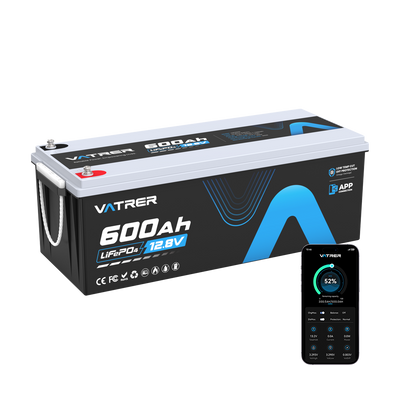
Replacement lithium batteries for RVs, boats, trolling motors, and golf carts are normally complete packs.
These packs combine cells, an internal BMS, temperature monitoring, terminals, and a protective enclosure. Bluetooth monitoring, internal heating, or low-temperature charge protection may also be included.
When comparing a Vatrer LiFePO4 lithium battery with other options, check voltage, usable energy, continuous current, surge requirements, charger compatibility, terminal layout, physical dimensions, and winter charging protection.
Which Integration Level Should You Choose?
Complete Packs for End Users
A complete pack is normally the best choice for an RV, cottage energy system, fishing boat, trolling motor, golf cart, or equipment replacement. It provides clearly stated voltage, current limits, charging requirements, terminals, and protection behaviour.
Modules for OEM and Custom System Projects
A module makes sense when an engineer or system integrator will design the master BMS, contactors, fusing, cooling system, enclosure, communication protocol, and charger interface.
Confirm the module’s full operating voltage range, sensor interface, communication requirements, temperature limits, and fault response before designing the rest of the system.
Cells for Experienced Battery Builders
Individual cells offer maximum flexibility but require a complete electrical and mechanical design. The builder must handle cell matching, busbars, insulation, compression, fusing, BMS configuration, temperature sensing, charging limits, and enclosure construction.
Lithium cells can release very high short-circuit current. A loose connection, reversed busbar, or dropped metal tool can cause severe heating and arcing. Use a complete tested pack when the required safety controls cannot be designed and verified.
Final Recommendation
A cell is the energy-storage unit, a module is an organized cell group, and a pack is the complete controlled battery.
Most consumers and installers should choose a finished pack. Modules are intended for engineered systems, while individual cells are best left to experienced builders and manufacturers.
Before ordering, identify your system voltage, required Wh, continuous load, surge load, installation dimensions, charger output, and lowest expected charging temperature. These specifications provide a far more reliable basis for selecting a battery than Ah capacity alone.
Share