Battery Cell vs Module vs Pack: What’s the Difference?
Reading time: 18 minutes

Share
A battery cell is the smallest unit that stores and releases electrical energy through an electrochemical reaction. A battery module joins several cells into a supported electrical assembly. A battery pack adds the control, protection, enclosure, and external connections needed to power real equipment.
That hierarchy is common, but it is not a fixed rule. Some packs connect cells directly inside the final enclosure and skip a separate module layer. The useful distinction is the level of integration: a cell stores energy, a module organizes cells, and a pack manages the complete power source.
What Is a Battery Cell?
A battery cell is the basic working unit inside a rechargeable battery. It accepts energy during charging, stores that energy chemically, and sends current through an external circuit during discharge.
One cell may be enough for a small electronic device. Larger systems combine many cells because one cell rarely provides the required voltage, capacity, or current on its own.
Core Function and Internal Components
A rechargeable lithium battery cell normally contains the following parts:
- Positive electrode: Its active material strongly affects voltage, energy density, safety, and cycle life.
- Negative electrode: It stores lithium ions while the cell charges.
- Electrolyte: It carries ions between the two electrodes.
- Separator: It keeps the electrodes apart while allowing ions to pass.
- Current collectors: They carry electrons from the active materials to the terminals.
- Terminals or tabs: They connect the cell to the rest of the circuit.
- Cell casing: It contains the internal materials and provides physical protection.
These parts work as one electrochemical unit. Change the electrode materials, and you may also change nominal voltage, power capability, charging behavior, temperature tolerance, and service life.
Common Cell Formats and Chemistries
Battery cells commonly use cylindrical, prismatic, or pouch construction. The format affects packaging and cooling, but it does not identify the chemistry by itself.
Common Battery Cell Formats
| Cell format | Physical construction | Main advantages | Design considerations |
|---|---|---|---|
| Cylindrical | Metal can with a rolled electrode assembly | Strong casing, standardized sizes, mature manufacturing | More gaps between cells and more individual connections |
| Prismatic | Rectangular metal enclosure | Good use of space and fewer cells for a given capacity | May need controlled compression and careful heat transfer |
| Pouch | Flexible laminated enclosure | Low casing weight and flexible dimensions | Needs external support and room for normal expansion |
Prismatic cells usually fit rectangular enclosures efficiently, while cylindrical cells simplify cell-level manufacturing and mechanical containment. Pouch cells save casing weight but place more responsibility on the surrounding structure.
Chemistry changes the electrical behavior. Typical nominal values include about 3.2V for LiFePO4, roughly 3.6V to 3.7V for many NMC or NCA lithium-ion cells, and about 2.3V for LTO.
Those values explain why a 12V-class LiFePO4 battery usually uses four cells in series, while a different lithium chemistry may need another series count to reach a similar pack voltage.
Voltage, Capacity, and Current Ratings
A battery cell has several separate ratings. You need all of them to understand what the cell can actually do.
- Nominal voltage describes the approximate operating voltage used for system calculations.
- Capacity in amp-hours, or Ah, describes stored charge under stated test conditions.
- Energy in watt-hours, or Wh, equals nominal voltage multiplied by Ah capacity.
- Continuous current is the current the cell can deliver without exceeding its limits.
- Peak current may be available only for a short period.
- Charge limits define the permitted voltage, current, and temperature range during charging.
A 3.2V 100Ah LiFePO4 cell stores about:
3.2V × 100Ah = 320Wh
That calculation gives nominal energy, not guaranteed runtime. Temperature, discharge rate, voltage cutoffs, wiring losses, and conversion losses all reduce the energy you can use at the load.
What Is a Battery Module?
A battery module combines several matched cells into an electrically connected and mechanically supported unit. It gives the cell group a defined voltage, capacity, shape, and thermal path.
Modules make large cell groups easier to assemble, test, cool, and install. A module may still need a pack-level controller, main protection devices, final enclosure, and external terminals before it can power equipment safely.
Cell Arrangement and Electrical Connections
Cells inside a module connect in series, parallel, or both. That connection pattern sets the module voltage, capacity, and current capability.
A typical module can include:
- Matched battery cells
- Copper or aluminum busbars
- Flexible or rigid interconnects
- Cell holders and spacers
- Compression plates for prismatic or pouch cells
- Electrical insulation
- Voltage-sensing wires
- A frame or module housing
Series connections raise voltage. Parallel connections raise Ah capacity and current capability. A series-parallel design can increase both.
Busbars deserve special attention because they carry the full module current. A busbar that is too small, poorly fastened, or unevenly loaded can create heat even when every cell is healthy.
Mechanical, Thermal, and Monitoring Components
A battery module has to control more than electrical connections. It also has to keep cells in position, manage heat, and maintain insulation under vibration and repeated temperature changes.
Mechanical features may hold cell spacing, control swelling, and transfer loads into a frame. Thermal parts may include cooling plates, thermal pads, airflow channels, or simple heat-conducting surfaces. Sensors may track temperature and cell-group voltage.
Some modules also contain local balancing circuits or a cell-monitoring board. That does not automatically make the module a complete battery pack. Main current control, charger communication, contactor operation, fault logging, and full-system protection often remain at pack level.
Cell Matching and Module Consistency
Cells in the same module share electrical stress. One weak cell can limit the useful capacity of the whole series string.
Manufacturers commonly compare cells by:
- Measured capacity
- Open-circuit voltage
- Internal resistance
- Self-discharge behavior
- Production batch and age
- Temperature response
Consider ten 100Ah cells connected in series. If one cell reaches its low-voltage limit after delivering 92Ah, the BMS may stop the module at about 92Ah even though the other cells still hold energy.
Cell matching reduces that gap. It also helps parallel cells share current more evenly and makes balancing easier over repeated charge cycles.
A simplified module build follows this sequence:
Cell inspection and matching → electrical connection → mechanical restraint and insulation → sensor installation → module testing
The quality of the finished module depends on each step. Good cells cannot compensate for a loose terminal, poor insulation, uneven compression, or a badly placed temperature sensor.
What Is a Battery Pack?
A battery pack is the complete battery system built for a final application. It may contain several modules, one module, or cells mounted directly inside the pack enclosure.
The pack turns stored cell energy into controlled power. It adds the switching, monitoring, protection, communication, and physical interfaces required by the vehicle, inverter, motor, appliance, or charger.


Integrated Components and External Interfaces
A complete battery pack may contain:
- Battery cells or modules
- Main busbars and internal wiring
- Positive and negative output terminals
- A battery management system
- Fuses or circuit breakers
- Contactors or MOSFET switching devices
- Current and temperature sensors
- A service disconnect
- A pre-charge circuit
- A mechanical enclosure
- Venting or pressure-relief features
- Communication ports
- Heating or cooling hardware
The exact component list depends on voltage and application. A compact 12V LiFePO4 battery may use MOSFET switching inside the BMS. A high-voltage EV battery needs contactors, isolation monitoring, pre-charge control, coolant connections, and a crash-resistant enclosure.
System-Level Protection and Control
The BMS keeps the battery pack inside its permitted operating range. It watches the cells and controls the path between the stored energy and the outside load.
Pack-level functions can include:
- Cell and pack voltage monitoring
- Current measurement
- Temperature monitoring
- Overcharge and over-discharge protection
- Overcurrent and short-circuit response
- Cell balancing
- State-of-charge estimation
- Contactor or MOSFET control
- Fault recording
- Communication with a charger, inverter, display, or vehicle controller
The BMS current rating can become the practical output limit. A pack with cells capable of 200A may still be limited to 100A continuous output if the BMS, terminals, busbars, or enclosure were designed for 100A.
Enclosure and Thermal Management
The enclosure protects the pack from the environment and keeps conductive parts isolated. It may need to handle vibration, moisture, dust, impact, salt exposure, and repeated temperature swings.
Thermal design depends on power level and operating conditions. A large traction battery may use liquid cooling. A lower-power LiFePO4 pack may rely on passive heat transfer, temperature sensors, and conservative current limits.
Cold charging needs separate attention. LiFePO4 chemistry can deliver power below freezing, but charging at low cell temperature may require a charge cutoff or internal heating. That protection comes from the pack design rather than the chemistry name alone.
Key Differences Between a Battery Cell, Module, and Pack
The main difference is how much of the battery system has already been built around the cells. The comparison below separates physical structure from actual operating function.
Battery Cell vs Module vs Pack
| Comparison point | Battery cell | Battery module | Battery pack |
|---|---|---|---|
| System level | Basic electrochemical unit | Intermediate assembly | Complete battery system |
| Main contents | Electrodes, separator, electrolyte, casing | Multiple cells, busbars, insulation, mechanical support | Cells or modules, BMS, protection devices, enclosure, external interfaces |
| Main role | Store and release energy | Connect and organize cells | Deliver controlled power to equipment |
| Voltage and capacity | Defined by one cell | Set by series and parallel layout | Set for the final system requirement |
| Monitoring | Usually no complete controller | May include sensors or local balancing | Usually includes system-level monitoring and control |
| Mechanical protection | Cell casing | Module frame or housing | Final environmental and installation enclosure |
| Thermal control | Limited to the cell and nearby structure | May include local cooling parts | Managed across the complete system |
| External connection | Cell tabs or terminals | Internal module connections | Load-ready terminals and communication |
| Ready for end use | Usually no | Usually no | Generally yes |
| Typical buyer | Cell maker, pack builder, engineer | OEM or system integrator | Consumer, installer, equipment maker |
If the component still needs a full BMS, main fuse, final enclosure, load terminals, and charger interface, it is not yet a complete battery pack, even if it already contains many cells.
Size and Level of Integration
Physical size usually increases from cell to module to pack, but size alone can mislead you. A large prismatic cell may be bigger than a compact electronics pack.
Integration level is the better test:
- The cell performs the electrochemical work.
- The module turns several cells into a controlled subassembly.
- The pack manages the subassemblies as one power source.
Components and System Functions
A module and a pack can both contain busbars, sensors, and structural parts. Their control scope separates them.
The module focuses on one cell group. Its structure holds those cells, and its sensors report local voltage or temperature. The pack controls the entire current path, decides when charge or discharge must stop, and communicates with the equipment.
A module with a monitoring board may still depend on an external master BMS. A finished pack normally exposes clear operating limits, load terminals, charge requirements, and fault behavior.
Voltage and Capacity
A single cell starts with one nominal voltage and one Ah rating. The module changes those values through series and parallel connections. The pack then combines the required cell groups to meet the final voltage, energy, runtime, and power target.
The cell count by itself tells you very little. Sixteen cells could form:
- 16S: higher voltage with one parallel path
- 8S2P: half the series count and twice the parallel capacity
- 4S4P: lower voltage with four parallel paths
The same number of cells can produce three very different battery systems.
Monitoring, Protection, and Thermal Control
Control becomes broader at each level.
- Cell level: Chemistry, separator design, internal construction, and operating limits provide the first layer of safety.
- Module level: Insulation, temperature sensing, voltage taps, mechanical support, and local balancing may protect one cell group.
- Pack level: The BMS, fuse, switching devices, current sensor, communication, and system-wide thermal strategy protect the complete battery.
The boundaries vary by manufacturer, so the control functions may not divide at exactly the same point in every design.
Installation and End Use
Bare cells need busbars, insulation, mechanical restraint, fusing, a BMS, an enclosure, and safe external connections. A module removes part of that work but may still depend on an external controller and final protective hardware.
A complete battery pack is normally the practical unit for an RV, boat, golf cart, solar battery bank, or equipment replacement. It should arrive with stated voltage, capacity, current limits, charging requirements, terminal layout, and protection behavior.
Serviceability and Replacement
A module-based pack can simplify fault isolation because technicians can test one section at a time. Replacement still requires electrical and software compatibility.
A serviceable module may need:
- Matching chemistry and nominal voltage
- Similar capacity and internal resistance
- A compatible communication interface
- Correct firmware or identification
- State-of-charge matching before connection
- BMS recalibration after installation
Mixing one new module with several aged modules can create imbalance. Small sealed packs are often replaced as complete units, while larger industrial systems may permit module-level work under controlled service procedures.
How Cells Form Modules and Battery Packs
Series and parallel connections turn low-voltage cells into useful battery systems. The arithmetic is simple, but the hardware still needs correct current ratings, insulation, cooling, and fault protection.
Series Connections and System Voltage
In a series connection, the positive terminal of one cell connects to the negative terminal of the next. The voltages add together.
For identical cells:
Total voltage = cell voltage × number of series cells
Total Ah capacity = capacity of one cell
Four 3.2V 100Ah LiFePO4 cells connected in series produce:
- Nominal voltage: 3.2V × 4 = 12.8V
- Capacity: 100Ah
- Nominal energy: 12.8V × 100Ah = 1,280Wh, or 1.28kWh
This arrangement is written as 4S.
Every series-connected cell carries the same current. If one cell reaches its upper or lower voltage limit early, the BMS must stop the string even if the remaining cells have room left.
Parallel Connections and Capacity
In a parallel connection, positive terminals join together and negative terminals join together. Voltage stays the same, while capacity adds.
Two 3.2V 100Ah cells in parallel provide:
- Nominal voltage: 3.2V
- Capacity: 200Ah
- Nominal energy: 640Wh
This arrangement is written as 2P.
Parallel cells share current. Differences in internal resistance, temperature, connection resistance, or wiring length can make one path work harder than another.
Do not connect cells or complete battery packs in parallel only because their labels show the same nominal voltage. The design must permit parallel operation, and the units need closely matched voltages before connection.
Series-Parallel Configurations
A series-parallel design raises voltage and capacity at the same time.
Example Configurations Using 3.2V 100Ah LiFePO4 Cells
| Configuration | Cell count | Nominal voltage | Capacity | Nominal energy |
|---|---|---|---|---|
| 4S | 4 | 12.8V | 100Ah | 1.28kWh |
| 4S2P | 8 | 12.8V | 200Ah | 2.56kWh |
| 8S | 8 | 25.6V | 100Ah | 2.56kWh |
| 16S | 16 | 51.2V | 100Ah | 5.12kWh |
| 16S2P | 32 | 51.2V | 200Ah | 10.24kWh |
The S count sets nominal voltage. The P count scales Ah capacity and the number of current-sharing paths. Two configurations with the same kWh can still need different chargers, inverters, cables, and protection devices because their voltage and current are different.
Conventional Modules and Cell-to-Pack Architecture
The cell-module-pack hierarchy remains common, but some designs remove the module layer to save space and parts.
Cell-to-Module-to-Pack Design
In a conventional layout, manufacturers build and test modules first, then install several modules inside a pack enclosure.
This architecture can offer:
- Separate module testing
- Flexible pack sizes based on module count
- Clear mechanical organization
- Easier section-by-section diagnosis
- Possible module-level repair
The extra layer also adds frames, covers, connectors, fasteners, and wiring. Those parts occupy space, increase weight, and create more electrical joints.
A module-based layout works well when production flexibility, service structure, and repeatable subassemblies matter more than maximum packaging efficiency.
Cell-to-Pack Integration
Cell-to-pack, often shortened to CTP, connects cells directly into the final pack structure without separate module housings.
Removing the intermediate layer can reduce component count and leave more enclosure volume for active cell material. It may also shorten the electrical path between cell groups.
The design places more responsibility on the pack structure. Cell restraint, isolation, heat control, fault containment, and service access all need to be solved at full-pack level.
Design and Service Trade-Offs
Packaging, manufacturing, and repair expose the main trade-offs:
Packaging
- Module-based design uses more frames and interfaces.
- CTP can improve space utilization and reduce structural parts.
Manufacturing
- Modules can be built and checked as separate subassemblies.
- CTP reduces assembly layers but demands tighter control during full-pack production.
Repair
- A module-based pack may allow one section to be isolated or replaced.
- Direct cell integration can make cell access and field repair more difficult.
Neither architecture guarantees better quality. Cell consistency, BMS logic, electrical isolation, thermal design, manufacturing accuracy, and fault containment still decide the result.
Cell, Module, and Pack Applications
Cell, module, and pack structures appear across vehicles, energy storage, RV systems, and electronics. Each application uses these layers differently.
Electric Vehicles and Industrial Systems
An EV traction pack may contain hundreds or thousands of cells. The exact count depends on cell size, chemistry, pack voltage, energy target, and series-parallel layout.
A complete traction pack can include:
- High-voltage cell strings
- Modules or direct cell integration
- Main contactors
- Current sensors
- Cooling and heating circuits
- High-voltage connectors
- Crash-resistant structure
- Vehicle communication
- Pack-level BMS
Industrial vehicles, telecom backup equipment, and large UPS systems often use module-based layouts because manufacturers can scale voltage or energy by changing the module count.
Energy Storage Systems
A rack-mounted energy storage unit may include an enclosure, BMS, terminals, communication ports, and a display.
A large installation may contain several layers:
- Cells inside a rack battery or module
- Several modules or packs in one rack
- Several racks in a cabinet or container
- A system controller, inverter, cooling system, and site-level protection
Before installation, check whether the listed unit needs an external master BMS, contactor box, inverter, charger, or protective cabinet. This check shows how much system integration still remains.
RV, Marine, and Golf Cart Batteries
Replacement lithium batteries for RVs, boats, trolling motors, and golf carts are normally complete battery packs sold as finished batteries.
The pack typically combines cells with an internal BMS, enclosure, terminals, temperature sensing, and defined charge and discharge limits. Bluetooth monitoring, internal heating, or a display may also be available, depending on the model.
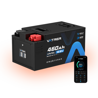
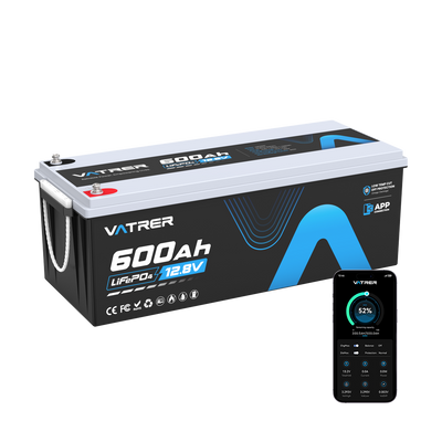
Such as the Vatrer LiFePO4 lithium battery, our battery that the product you install is a finished pack rather than a loose cell group. Compare nominal voltage and required runtime first, then check continuous current, peak demand, charger compatibility, dimensions, terminal layout, and low-temperature behavior.
Consumer Electronics and Power Tools
A smartphone may use one pouch cell with a protection circuit and outer wrapping. The finished assembly is still called a battery pack because it connects directly to the device as a controlled power unit.
Laptops and cordless tools often use several cells inside one final enclosure. They may not contain a separately removable module.
That distinction explains why a six-cell tool battery is normally a pack rather than a module: it already includes the casing, terminals, protection electronics, and mechanical interface required by the tool and charger.
Choosing Between Cells, Modules, and Complete Packs
Choose the lowest integration level only if you are prepared to design everything that still remains above it.
Complete Battery Packs for End Users
A finished battery pack is usually the right choice for an RV, boat, golf cart, trolling motor, solar system, or equipment replacement.
Compare these specifications before buying:
- Nominal voltage
- Ah capacity and Wh energy
- Continuous and peak discharge current
- BMS current limits
- Charge voltage and recommended charge current
- Low-temperature protection
- Series and parallel limits
- Communication or monitoring features
- Dimensions, weight, and terminal layout
- Warranty and application compatibility
Once you know the motor, inverter, or equipment demand, you can choose a pack whose BMS, terminals, internal connections, and thermal design can carry that current without nuisance shutdowns.
Battery Modules for OEMs and System Integrators
A battery module fits projects where the pack-level system will be engineered around it.
The remaining work can include:
- Master BMS architecture
- Main contactors and pre-charge control
- Fusing and service disconnects
- Final enclosure
- Cooling or heating
- Communication protocols
- Charger or inverter integration
- Certification and system testing
A module may fit the available space and still be incompatible with the controller. Confirm its operating voltage range, sensing interface, communication method, cooling requirements, and fault response before building the rest of the system.
Individual Cells for Qualified Builders
Individual cells provide the greatest freedom over shape, voltage, capacity, and current capability. They also leave nearly every safety decision unfinished.
A cell-based build requires knowledge of:
- Cell selection and matching
- Series and parallel design
- Busbar sizing
- Connection resistance
- Compression and mechanical support
- Electrical insulation
- Short-circuit protection
- BMS selection and configuration
- Temperature sensing
- Charging limits
- Enclosure design
- Final electrical testing
Large lithium cells can release very high fault current. A dropped tool, reversed busbar, loose connection, or exposed conductor can cause intense heating and arcing.
Choose a complete tested pack if you cannot define the fuse rating, conductor size, BMS limits, compression method, charging profile, and safe fault response before assembly.
Common Terminology Misconceptions
The following distinctions help prevent confusion between cells, modules, packs, and larger battery systems.
- “Battery” may mean a cell or a pack. An AA battery is commonly one cell, while an EV battery is a large pack.
- A battery module may not have a complete BMS. It may contain only sensors, balancing circuits, or a monitoring board.
- A battery pack may not contain separate modules. CTP designs connect cells directly into the pack.
- A battery module and a modular battery system are different concepts. A modular system lets you add, remove, stack, or parallel complete units.
- Rack batteries may integrate a BMS, enclosure, terminals, and communication features.
- More cells do not automatically mean better performance. Chemistry, matching, internal resistance, BMS limits, cooling, and connection quality matter.
- Nominal voltage is not maximum charge voltage. A 12.8V LiFePO4 pack normally charges above its nominal rating.
- Ah is not energy. Multiply nominal voltage by Ah to compare Wh across different voltage systems.
Final Recommendation
Start with the work that remains unfinished. A complete battery pack is the sensible choice when you need a tested unit with defined terminals, current limits, charging requirements, and protection. A battery module belongs in a larger engineered system. Individual cells leave the full electrical, mechanical, and safety design in your hands.
Before ordering, write down six values: system voltage, required Wh, continuous load current, peak current, available installation space, and charger output. Those figures will tell you which pack specification fits the job and whether a module or cell-level build is worth the extra engineering.
Share