What Materials Are Used In Lithium-Ion Batteries?
Reading time: 19 minutes

Share
A lithium-ion battery contains much more than lithium. Inside each cell, a lithium-bearing cathode works with an anode, electrolyte, separator, metal current collectors, conductive carbon, binders, and a protective casing. A complete battery adds busbars, wiring, insulation, sensors, control electronics, and an outer enclosure.
The exact recipe changes with the chemistry. LiFePO4 cells use iron and phosphate in the cathode. NMC cells use nickel, manganese, and cobalt. Some lithium-ion batteries contain no cobalt or nickel, and conventional cells normally do not contain a metallic lithium anode.
Lithium-Ion Battery Materials at a Glance
Each material has a narrow job. The electrodes store energy, the electrolyte carries lithium ions, the separator keeps the electrodes apart, and the metal foils carry electrons.
Main Materials in a Lithium-Ion Cell
| Component | Common Materials | Typical Form | Primary Job |
|---|---|---|---|
| Cathode | LFP, NMC, NCA, LCO, LMO | Powder coating on aluminum foil | Releases and receives lithium ions |
| Anode | Graphite, silicon-graphite, LTO | Powder coating on copper or aluminum foil | Stores lithium ions during charging |
| Electrolyte | Lithium salt, carbonate solvents, additives | Liquid absorbed into the electrodes and separator | Carries lithium ions |
| Separator | PE, PP, ceramic-coated polymer | Porous film, often 12–25 µm thick | Prevents electrode contact |
| Cathode current collector | Aluminum | Foil, often 8–15 µm thick | Conducts electrons |
| Anode current collector | Copper | Foil, often 6–12 µm thick | Conducts electrons |
| Conductive additive | Carbon black, conductive graphite | Fine powder in the electrode coating | Builds electron pathways |
| Binder | PVDF, CMC, SBR | Polymer in the electrode coating | Holds particles on the foil |
| Cell casing | Steel, aluminum, polymer laminate | Rigid can or flexible pouch | Protects the cell layers |
The energy-storing materials are only part of the cell. Separator film, metal foils, binder, carbon, tabs, and casing do not add much capacity, yet the cell cannot operate reliably without them.
During charging, lithium ions move from the cathode toward the anode through the electrolyte. During discharge, they travel back to the cathode. Electrons take a different path through the external circuit, where they power the connected load.
Core Materials Inside a Lithium-Ion Batteries Cell
The cathode creates most of the chemistry-level differences between lithium-ion cells. The anode and electrolyte then shape charging behavior, usable capacity, cycle life, and temperature performance.
Cathode Materials
The cathode material in lithium-ion batteries affects nominal voltage, energy density, thermal behavior, service life, and raw-material cost. Manufacturers choose among several established lithium-ion battery cathode materials, each with a different balance of properties.
Lithium Iron Phosphate
Lithium iron phosphate is commonly abbreviated as LFP or LiFePO4. Its cathode contains lithium, iron, phosphorus, and oxygen.
The phosphate structure is chemically stable and resists oxygen release better than many layered metal-oxide cathodes. That helps LFP cells tolerate heat and repeated cycling. A typical LFP cell has a nominal voltage of about 3.2V.
Its main characteristics include:
- no nickel or cobalt in the cathode;
- long cycle life under suitable operating conditions;
- relatively stable high-temperature behavior;
- lower energy density than many NMC or NCA cells;
- a flat discharge-voltage curve.
Four LFP cells in series create a nominal 12.8V battery:
4 × 3.2V = 12.8V
Sixteen cells create a nominal 51.2V battery:
16 × 3.2V = 51.2V
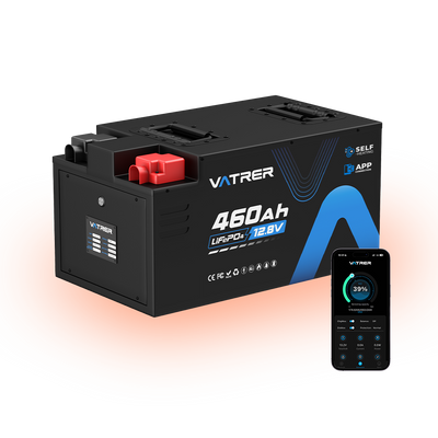
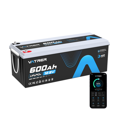
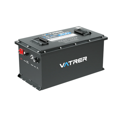
That series arrangement is common in RV, golf cart, marine, solar storage, and backup-power batteries. Vatrer uses LiFePO4 across many deep-cycle applications because these systems usually benefit more from long service life and thermal stability than from the highest possible energy density.
Nickel Manganese Cobalt
NMC cathodes contain lithium, nickel, manganese, cobalt, and oxygen. The three transition metals do not contribute in exactly the same way.
Nickel generally raises capacity. Manganese can support structural and thermal stability. Cobalt helps maintain the layered cathode structure and supports consistent electrochemical performance.
NMC labels describe the ratio of nickel, manganese, and cobalt:
- NMC111: approximately equal portions of all three metals;
- NMC622: about 60% nickel, 20% manganese, and 20% cobalt;
- NMC811: about 80% nickel, 10% manganese, and 10% cobalt.
A higher nickel percentage can increase capacity and reduce cobalt content. It may also make the material more sensitive to moisture, high voltage, surface reactions, and elevated temperature. Particle coatings, electrolyte formulation, cell design, and cooling become more demanding as nickel content rises.
Nickel Cobalt Aluminum
NCA cathodes use lithium, nickel, cobalt, aluminum, and oxygen. Their high nickel content supports high specific energy, while aluminum helps stabilize the crystal structure.
NCA works well where low weight and high energy storage are major priorities. The chemistry is less forgiving of poor temperature control or aggressive voltage limits, so the surrounding battery system carries a larger share of the safety burden.
Lithium Cobalt Oxide
LCO contains lithium, cobalt, and oxygen. Its high volumetric energy density suits compact products such as phones, tablets, and laptops.
The chemistry has clear limits:
- cobalt raises material cost and supply-chain exposure;
- cycle life is often lower than that of LFP;
- high states of charge increase thermal stress;
- large-format deep-cycle systems rarely favor LCO.
LCO remains useful when a small physical size matters more than long deep-cycle life.
Lithium Manganese Oxide
LMO uses a manganese-based spinel structure. Lithium ions can move through that structure quickly, which supports high power output.
Its advantages include good rate capability and relatively stable thermal behavior. The trade-off is faster capacity loss in some designs, partly because manganese can dissolve into the electrolyte over time. Manufacturers sometimes blend LMO with NMC to combine power capability with higher energy storage.
Anode Materials
The anode receives lithium ions during charging and releases them during discharge. Its material affects capacity, fast-charging limits, low-temperature behavior, and the rate of long-term capacity loss.
Graphite
Graphite remains the standard anode material in most commercial lithium-ion batteries. Lithium ions fit between its carbon layers through a reversible process called intercalation.
Graphite has a theoretical capacity of about 372 mAh/g. That number is much lower than silicon’s theoretical capacity, yet graphite offers a practical mix of stability, cost, processing maturity, and cycle efficiency.
Its value comes from several properties:
- a layered structure that can repeatedly host lithium ions;
- a low operating potential that supports good cell voltage;
- limited dimensional change compared with silicon;
- a relatively stable solid electrolyte interphase;
- mature natural-graphite and synthetic-graphite supply chains.
Electrical conductivity helps, but it is not the main reason graphite dominates commercial anodes. Reversible lithium storage is the defining feature.
Silicon-Graphite Blends
Silicon can theoretically store about 3,579 mAh/g, nearly ten times the gravimetric capacity of graphite. A finished battery will not gain ten times more energy, because the cathode, current collectors, electrolyte, separator, casing, and safety margins still limit total cell capacity.
The larger problem is expansion. Silicon can swell by close to 300% as it absorbs lithium. Repeated swelling and contraction may:
- crack silicon particles;
- break contact between particles;
- damage the binder network;
- rupture and rebuild the protective surface layer;
- consume electrolyte and active lithium.
Commercial anodes usually mix a limited amount of silicon or silicon oxide with graphite. Carbon coatings, porous structures, elastic binders, and pre-lithiation can improve life, though each method adds manufacturing difficulty.
Lithium Titanate
Lithium titanate, or LTO, replaces graphite in the anode. Its theoretical capacity is about 175 mAh/g, well below graphite and silicon.
LTO operates at a higher potential than graphite. That reduces lithium-plating risk and supports fast charging, long cycle life, and good low-temperature performance. The same higher potential lowers complete-cell voltage, often to around 2.3–2.4V.
LTO therefore suits specialized applications where rapid charging and very long service life outweigh battery size and weight.
Comparison of Common Anode Materials
| Anode Material | Approximate Theoretical Capacity | Main Advantage | Main Limitation |
|---|---|---|---|
| Graphite | 372 mAh/g | Stable and commercially mature | Moderate capacity |
| Silicon | 3,579 mAh/g | Very high lithium-storage capacity | Severe volume expansion |
| Silicon-graphite blend | Varies with silicon content | Higher capacity than graphite alone | More swelling and interface degradation |
| Lithium titanate | About 175 mAh/g | Fast charging and long cycle life | Low complete-cell voltage |
Graphite remains the default choice because it gives the most balanced commercial result. Silicon works mainly as a capacity-boosting addition, while LTO serves a narrower fast-charge and long-life role.
Electrolyte Materials
The electrolyte fills the pores in the electrodes and separator. It carries lithium ions but blocks normal electron flow. Most liquid electrolytes contain three material groups.
Lithium Salts
Lithium hexafluorophosphate, written as LiPF6, is widely used in conventional lithium-ion cells. Typical electrolyte concentrations are often around 1.0–1.2 mol/L.
Other salts include:
- LiBF4;
- LiFSI;
- LiTFSI.
Each salt behaves differently in conductivity, heat tolerance, high-voltage stability, aluminum compatibility, moisture sensitivity, and cost.
Organic Solvents
The lithium salt dissolves in a blend of carbonate solvents. Common examples include:
- ethylene carbonate;
- dimethyl carbonate;
- diethyl carbonate;
- ethyl methyl carbonate.
One solvent may support stable interface formation, while another lowers viscosity and improves lithium-ion movement. Commercial electrolytes usually combine several solvents rather than relying on one liquid.
These organic solvents are generally flammable. That does not mean every cell will catch fire, but it does make separator quality, voltage control, thermal design, and fault protection more significant.
Electrolyte Additives
Additives make up a relatively small part of the electrolyte, yet they can change cell behavior noticeably.
They may help:
- form a more stable surface layer on the anode;
- reduce gas generation;
- improve low-temperature charging;
- protect high-voltage cathodes;
- slow electrolyte breakdown.
Exact additive packages are usually proprietary. Two cells with the same cathode and anode chemistry may perform differently because their electrolyte formulations are not identical.
Heat, high voltage, and long storage at a high state of charge accelerate unwanted electrolyte reactions. Those reactions can raise internal resistance, consume active lithium, and create gas inside the casing.
Separator Materials
The separator is a porous electrical insulator between the cathode and anode. It allows lithium ions to move through electrolyte-filled pores while stopping direct electronic contact.
Common separator materials include:
- polyethylene, or PE;
- polypropylene, or PP;
- multilayer PE/PP films;
- ceramic-coated polymer films.
Commercial separator thickness often falls between 12 and 25 µm, equal to 0.012–0.025 mm. A thinner separator can reduce ionic resistance and leave more room for active material. It also gives the cell less tolerance for pinholes, contamination, uneven coating, or physical damage.
Separator performance depends on several linked properties:
- Porosity controls how much electrolyte the film can hold.
- Pore structure affects lithium-ion movement.
- Puncture resistance helps the film survive mechanical stress.
- Thermal shrinkage influences behavior during overheating.
- Electrolyte wettability affects ion transport across the cell.
Ceramic coatings can improve heat resistance and dimensional stability. They do not make a cell immune to internal shorts, overcharging, crushing, or manufacturing defects.
Current Collectors and Electrode Additives
Cathode and anode active materials start as powders. Manufacturers turn them into usable electrodes by combining them with binders and conductive additives, then coating the mixture onto metal foil.
Current Collectors
Aluminum foil normally supports the cathode. Copper foil normally supports a graphite or silicon-based anode.
Typical foil thicknesses often fall within these ranges:
- cathode aluminum foil: 8–15 µm;
- anode copper foil: 6–12 µm.
The two metals are not interchangeable in ordinary cell designs. Aluminum remains stable at cathode potentials and weighs less than copper. At the low operating potential of a graphite anode, aluminum can react with lithium, so copper is used instead.
LTO anodes operate at a higher potential and may use aluminum current collectors.
Conductive Additives
Many cathode powders do not conduct electrons well enough on their own. Carbon black, conductive graphite, or other carbon materials create pathways between active particles and the metal foil.
More conductive carbon can lower resistance, but it also takes up space that could hold active material. Electrode designers must balance power capability against energy density.
Electrode Binders
Binders hold active particles and conductive carbon on the current collector.
Common examples include:
- PVDF in many cathodes;
- CMC and SBR in water-processed graphite anodes;
- more elastic binder systems in silicon-containing anodes.
Too little binder can lead to cracking, weak adhesion, and particle loss. Too much reduces the proportion of active material and may raise resistance.
Material Differences Across Battery Chemistries
A chemistry name usually identifies a main electrode material. It does not describe every component inside the cell.
Common Lithium-Ion Chemistry Comparison
| Chemistry | Key Cathode Elements | Common Anode | Typical Nominal Cell Voltage | Main Strength | Main Trade-Off |
|---|---|---|---|---|---|
| LFP | Lithium, iron, phosphorus, oxygen | Graphite | About 3.2V | Long cycle life and strong thermal stability | Lower energy density |
| NMC | Lithium, nickel, manganese, cobalt, oxygen | Graphite or silicon-graphite | About 3.6–3.7V | Balanced energy and power | Nickel and cobalt dependence |
| NCA | Lithium, nickel, cobalt, aluminum, oxygen | Graphite or silicon-graphite | About 3.6V | High energy density | Demanding thermal control |
| LCO | Lithium, cobalt, oxygen | Graphite | About 3.6–3.7V | High volumetric energy density | Cobalt cost and moderate cycle life |
| LMO | Lithium, manganese, oxygen | Graphite | About 3.7–3.9V | Strong power capability | Faster capacity fade in some designs |
| LTO | Cathode varies | Lithium titanate | About 2.3–2.4V | Fast charging and long cycle life | Low energy density |
The practical dividing line is clear. LFP favors cycle life, thermal stability, and lower dependence on nickel and cobalt. NMC and NCA favor higher energy density. LTO sacrifices size and weight for fast charging and long service life.
Two cells with the same chemistry label can still behave differently. Particle size, surface coating, electrode thickness, electrolyte additives, separator quality, manufacturing cleanliness, and formation procedures all influence the finished cell.
Materials Beyond the Lithium-ion Battery Cell
A cell is the electrochemical unit. A battery pack combines one or more cells with electrical connections, mechanical support, control electronics, and protective materials.
Cell Casings
Cell format determines the casing material and how the battery handles pressure, heat, and mechanical stress.
- Cylindrical cells commonly use nickel-plated steel cans. The rigid shell can include a vent and current-interrupt device.
- Prismatic cells often use aluminum housings. Their flat shape uses enclosure space efficiently but may need controlled compression.
- Pouch cells use multilayer aluminum-polymer laminate. The light casing improves cell-level energy density, while the pack must provide more mechanical support.
The casing does not change the underlying chemistry. It does affect weight, cooling, impact resistance, swelling control, and pack assembly.
Battery Pack Structures
A complete battery may contain:
- copper or aluminum busbars;
- copper cables and terminals;
- polymer or fiber insulation;
- steel, aluminum, or molded-polymer enclosures;
- cell holders and compression plates;
- seals, gaskets, vents, and mounting hardware.
Electrical resistance depends on busbar dimensions, joint quality, weld consistency, contact pressure, and corrosion control. A poor connection can create more heat than the cell itself under high current.


Thermal and Control Materials
Battery packs may use thermal pads, heat spreaders, cooling plates, liquid coolants, flame-resistant barriers, temperature sensors, circuit boards, and semiconductor switches.
The battery management system monitors:
- cell voltage;
- pack current;
- cell temperature;
- charge and discharge limits;
- cell balance;
- fault conditions.
These parts do not add energy capacity. They determine how much of the stored energy the battery can use safely under real operating conditions.
Vatrer batteries use this Grade A cell chemistry, which provides the energy-storage foundation, while protection electronics, enclosure design, current paths, and temperature controls shape the finished product.
How Material Choice Affects Lithium-ion Battery Performance
A material can improve one performance area while creating a new trade-off elsewhere. Higher capacity may bring more swelling. Higher voltage may increase electrolyte stress. Greater thermal stability may come with lower energy density.
Energy and Voltage
Battery energy is calculated from voltage and capacity:
Energy in watt-hours = voltage × amp-hours
A 100Ah LFP cell at 3.2V stores about:
3.2V × 100Ah = 320Wh
A 100Ah cell at 3.6V stores about:
3.6V × 100Ah = 360Wh
At the same amp-hour capacity, the 3.6V cell contains 12.5% more nominal energy:
(360Wh − 320Wh) ÷ 320Wh × 100 = 12.5%
That simple comparison does not include weight, allowed voltage range, casing, cooling hardware, or inactive materials. It shows why cathode voltage has a direct effect on watt-hours.
Broad cell-level energy-density ranges often fall around:
- LFP: 90–160Wh/kg;
- NMC: 150–250Wh/kg;
- LCO: 150–200Wh/kg.
A finished battery pack usually has a lower Wh/kg figure because the enclosure, busbars, wiring, cooling parts, and control electronics add weight without adding cell capacity.
Charging and Cycle Life
Fast charging depends on the entire ion pathway. Lithium ions must move through the electrolyte, cross the electrode surface, diffuse into active particles, and occupy available storage sites.
Several design choices influence that process:
- smaller particles shorten diffusion distance;
- suitable porosity gives electrolyte access to the electrode;
- conductive carbon lowers electronic resistance;
- a stable surface layer limits unwanted reactions;
- thinner electrodes reduce transport distance;
- thicker electrodes hold more energy per sheet but can charge less evenly.
Low temperature slows lithium-ion movement and charge-transfer reactions. Charging too aggressively can deposit metallic lithium on the anode surface instead of storing it between graphite layers.
Cycle-life claims need context. A battery tested at shallow depth of discharge and moderate temperature may last far longer than the same chemistry under full-depth cycling, high current, or heat. Voltage limits and the chosen end-of-life threshold also change the result.
This is where a complete product specification matters more than a chemistry label. Vatrer battery selection should be based on your system voltage, expected current, operating temperature, daily depth of discharge, and charging source rather than one advertised cycle number.
Safety and Temperature
Cathode chemistry is one part of battery safety. Electrolyte flammability, separator strength, internal contamination, state of charge, wiring quality, enclosure design, and BMS response also matter.
LFP generally has better thermal stability than layered nickel- and cobalt-based cathodes. That lowers one source of risk, but LFP batteries can still fail after:
- severe overcharge;
- internal short circuit;
- physical crushing or puncture;
- external fire;
- incorrect system wiring;
- defective cells or connections.
Cold-weather charging creates a different problem. The anode may accept lithium ions too slowly below freezing, raising the risk of lithium plating. Heating elements and low-temperature charging controls can protect the cells without changing the LiFePO4 cathode material itself.
Cost, Availability, and Purity
Iron- and phosphate-based cathodes avoid nickel and cobalt, which can lower material cost and reduce exposure to those supply chains. NMC and NCA use more expensive metals to achieve higher energy density.
Raw materials are only one part of battery price. The finished cost also includes:
- refining and cathode synthesis;
- electrode coating and drying;
- separator and electrolyte production;
- cell formation and quality testing;
- casing, terminals, and busbars;
- BMS hardware;
- enclosure and thermal parts;
- assembly, certification, shipping, and warranty support.
Material purity can change performance even when the chemical name stays the same. Battery-grade powders require tight control of moisture, metal contamination, particle size, and residual processing chemicals.
Trace water can react with electrolyte ingredients. Conductive metal particles may create local short-circuit paths. Uneven particle size can produce uneven current density and faster degradation.
Intentional doping is different from contamination. Engineers may add a controlled amount of another element to change conductivity or structural stability. Uncontrolled contamination introduces variation without a designed benefit.
Sustainability and Recycling of Lithium-ion Batteries
The main lithium-ion battery raw materials include lithium, graphite, nickel, cobalt, manganese, copper, aluminum, iron, and phosphorus. Different chemistries place demand on different parts of that list.
Critical Minerals
LFP removes nickel and cobalt from the cathode, but it still needs lithium, graphite, copper, aluminum, electrolyte chemicals, iron compounds, and phosphate materials.
NMC and NCA rely on nickel and cobalt to reach higher energy density. That can reduce cell mass for a given energy target, though the metals bring higher cost and more complex sourcing.
The environmental footprint depends on more than mining. Refining, cathode production, graphite processing, electricity sources, cell manufacturing yield, transport distance, and usable battery life all affect the result.
A long-lived battery may spread its manufacturing impact across more charge-discharge cycles. That benefit disappears if the battery is poorly matched to the application or replaced early because of heat, incorrect charging, or inadequate protection.
Material Recovery
Lithium-ion battery recycling can recover several useful materials:
- copper and aluminum from foils, terminals, and enclosures;
- nickel, cobalt, and manganese from cathodes;
- lithium from processed cathode material and electrolyte residues;
- steel from some cell casings;
- graphite through selected recovery methods.
The economics vary by chemistry. Nickel- and cobalt-rich batteries contain metals with relatively high recovery value. LFP recycling depends more heavily on efficient collection, low processing cost, large volumes, and methods that preserve or restore the cathode material.
Used lithium-ion batteries should not go into household garbage or curbside recycling bins. Compaction, crushing, or contact with metal waste can damage the cells and start fires. Use a battery collection point or hazardous-waste service that accepts the exact battery type.
What Are Some Emerging Lithium-Ion Battery Materials
Current commercial cells still rely heavily on graphite anodes, liquid carbonate electrolytes, polyolefin separators, and established cathode families. New materials aim to increase capacity or reduce flammability, but they bring their own manufacturing problems.
Silicon-rich anodes raise anode capacity by increasing the silicon content. Swelling, surface-layer damage, and loss of electrical contact remain the main limits.
Solid electrolytes use ceramic, sulfide, polymer, or composite materials to conduct lithium ions. They can reduce the amount of flammable liquid inside the cell. Interface resistance, thin-layer production, pressure requirements, moisture sensitivity, and durability still limit large-scale use.
Lithium-metal anodes have a theoretical capacity of about 3,860 mAh/g. That figure is higher than graphite and slightly higher than silicon, but unstable deposition and dendrite growth can create internal-short risks. Conventional lithium-ion batteries normally use graphite or silicon-graphite rather than metallic lithium.
Sodium-ion, potassium-ion, magnesium, lithium-sulfur, and iron-air batteries use different charge carriers or reaction mechanisms. They belong to separate battery systems rather than ordinary lithium-ion material variations.
Common Misunderstandings About Lithium Battery Materials
- A lithium-ion battery is not made mostly from metallic lithium.
- Lithium is usually present in cathode compounds and electrolyte salts.
- LFP batteries do not contain cobalt or nickel in the cathode.
- The electrolyte is not liquid lithium.
- Graphite is an active lithium-storage material, not merely a filler.
- The separator carries lithium ions through electrolyte-filled pores but does not conduct electrons.
- Ceramic coating can improve separator heat resistance without making the cell fireproof.
- A chemistry label does not describe cell quality, BMS quality, or pack construction.
- Cell materials and battery pack materials are different categories.
- A material safety data sheet for lithium-ion batteries should match the exact cell or battery product. One generic document may not cover the same chemistry, enclosure, capacity, or transport classification.
Final Summary
Use the chemistry to identify the basic trade-off, then look beyond the chemistry name. Check nominal voltage, usable energy, operating-temperature limits, permitted charge rate, cycle-test conditions, BMS ratings, enclosure design, and safety documentation.
LFP is often the stronger fit for frequent deep cycling, stationary storage, RVs, golf carts, and marine systems where life and thermal stability carry more weight than minimum size. NMC and NCA make more sense where higher energy density can justify tighter thermal and voltage control. LTO serves a smaller group of applications that place fast charging and extreme cycle life above weight.
At Vatrer, we recommend choosing the complete battery around the load, charging source, temperature range, and daily usage pattern. A metal name or chemistry label can narrow the options, but the full battery design determines how well the system performs after installation.
Share